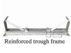
Conveyor Impact Roller Manufacturers | GCS
GCS Conveyor Supply offers a wide range of rollers to fit most conveyor applications - designed to the highest industry standards. Roller materials, lengths, diameters, and trough options can be customized to meet customer specifications. We are a manufacturer of slotted rollers, rollers, and frames. Our factory can do it all for bulk material companies, making it simple for everyone to design and order custom rollers and affordable matching roller frames online.
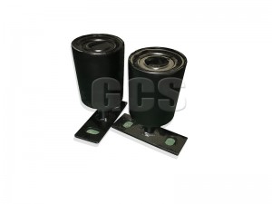
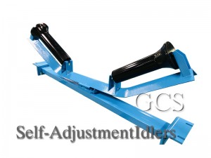
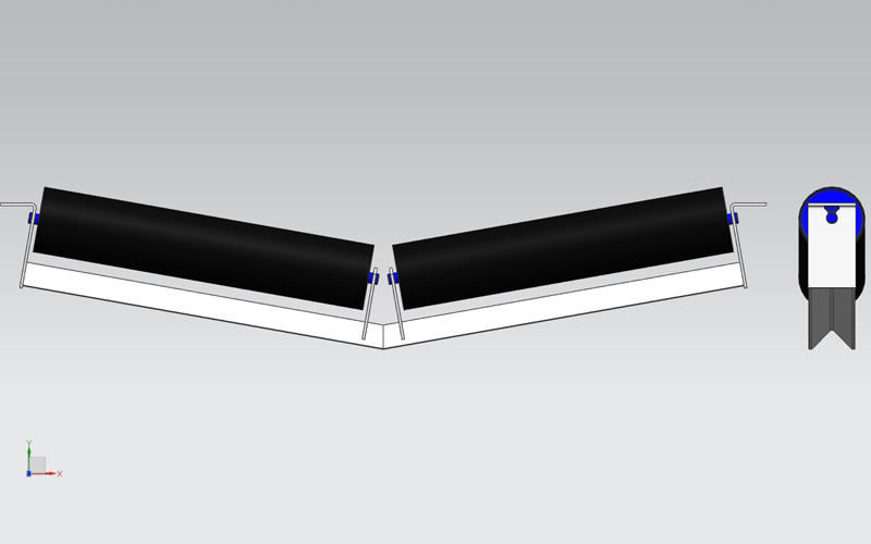
The Equal Trough impact idler, a conventional type carrier roller set, consists of three equal-length impact idlers supporting three rollers in one frame that is fixed to the conveyor structure. In quarry and mining applications, when large, heavy, and sharp materials fall on the conveyor, they can impact and damage the belt, ultimately leading to downtime and higher replacement costs. Therefore, an impact idler is needed in the material impact area.
It is designed with a rubber ring to provide cushioning and absorb impact in the material impact area, minimizing damage to the belt.
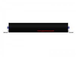
The impact idler sets are typically spaced 350 mm to 450 mm apart to provide overall support. It is installed in the first roller group at the conveyor's drop gate.
Applications
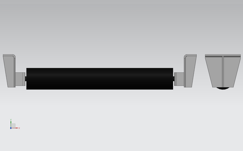
Conveyor impact rollers are used for belt conveyors to receive materials and reduce and slow down the impact of the conveyor belt, mainly designed for corrosive environments such as coal washing plants, coking plants, and chemical plants. The impact rollers have good corrosion resistance and if used in corrosive situations, their service life is five times that of ordinary rollers.
Get high-quality conveyor rollers, custom conveyor rollers, matching roller supports, and more you need.
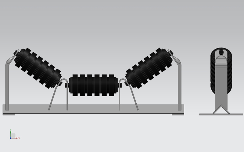
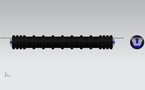
lmpact rollers set
lmpact rollers are used and positioned corresponding to the load points, where the lumps and the weight of material fling onto the belt could in fact cause damage to it.To limit the impact effect of the material onto the rollers, the atter are covered with a series of rubber rings of adequate thickness and resistance.
Impact rollers are under stress not only from the load of the material, but also from the dynamic forces as the loadalls onto the belt. The impact onto the belt, arising from the free fall of material will be naturally greater than in the case where the material is deflected onto the belt by an inclined.
For the correct dimension and the choice of impact rollers in relation to the load check the characteristics of the base roller.
Material Iron
Application Chemical Industry| Grain Transportation|Mining Transport|Power
Plant|Structure Ordinary Roller|Bearing Type|Double Sealed Bearing
Type:Impact Idler
Product Name:Impact Idler Roller
Usage:Conveyor Belt System
Diameter:50-219 mm
Surface Preparation:Spray Paint
Color:Requirements
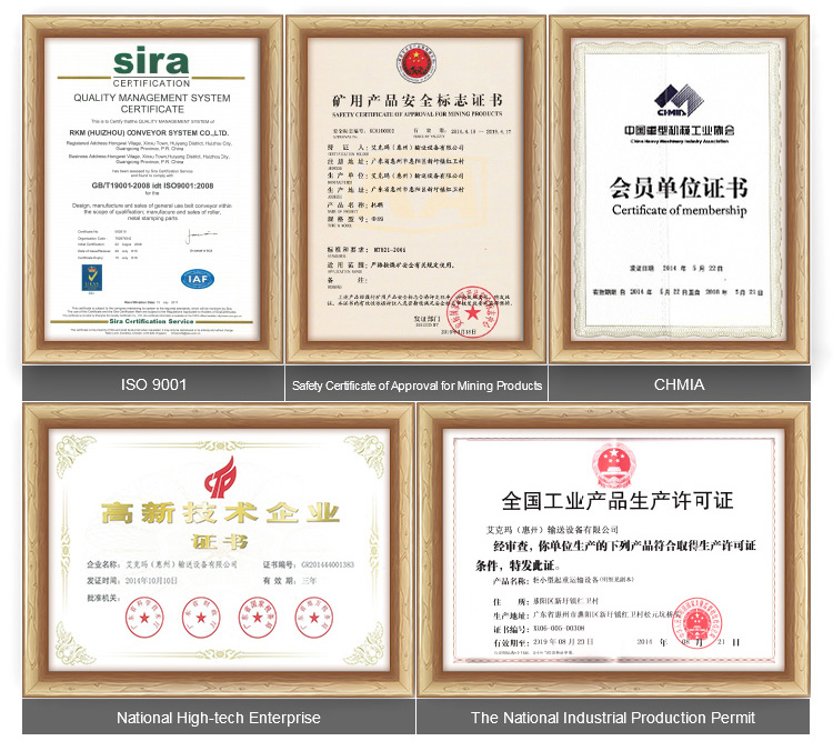
Certification:ISO 9001 : 2015
Trademark: GCS
HS Code:8431390000
Trough Idler -SERIES RS/HRS
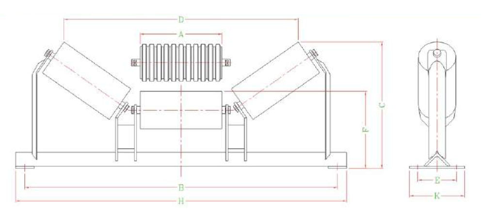
3 ROLL TROUGH IDLERS-152 DIAMETER
| Code No. | A | B | 20° | 30° | 35° | 45° | Base Angle Size | Shaft Dia. | Trough Mass | Total | Shaft Dia. | Impact Mass R.P. | Total Mass | ||||
| C | D | C | D | C | D | C | D | R.P. | Mass | ||||||||
| XX-A1-3-C2A2-0750-YY | 283 | 1000 | 106 | 856 | 144 | 818 | 164 | 782 | 194 | 694 | 75 | 27 | 17.6 | 35.2 | 38 | 23.7 | 46.2 |
| XX-A1-3-C2A2-0800-YY | 299 | 1050 | 106 | 892 | 159 | 860 | 179 | 818 | 206 | 736 | 75 | 27 | 18.1 | 36.4 | 38 | 24.8 | 48.5 |
| XX-A1-3-C2A2-0900-YY | 336 | 1150 | 117 | 1016 | 175 | 962 | 196 | 922 | 235 | 818 | 75 | 27 | 19.2 | 38.8 | 38 | 24.7 | 53.1 |
| XX-A1-3-C2A2-1000-YY | 363 | 1250 | 127 | 1092 | 188 | 1038 | 215 | 988 | 256 | 882 | 75 | 27 | 20.3 | 41.2 | 38 | 27.2 | 57.7 |
| XX-A1-3-C2A2-1050-YY | 388 | 1300 | 142 | 1162 | 204 | 1104 | 226 | 1058 | 270 | 946 | 75 | 27 | 21.4 | 43.1 | 38 | 28.5 | 60.4 |
| XX-A1-3-C2A2-1200-YY | 441 | 1450 | 157 | 1314 | 224 | 1252 | 260 | 1192 | 311 | 1068 | 75 | 27 | 23.8 | 47.5 | 38 | 32.4 | 67.6 |
| XX-A1-3-D2A3-1350-YY | 493 | 1650 | 177 | 1462 | 255 | 1392 | 283 | 1338 | 346 | 1196 | 90 | 30 | 26.0 | 55.0 | 38 | 35.2 | 76.6 |
| XX-A1-3-D2A3-1400-YY | 499 | 1700 | 177 | 1484 | 255 | 1414 | 295 | 1342 | 346 | 1224 | 90 | 30 | 26.3 | 56.6 | 38 | 35.7 | 77.7 |
| XX-A1-3-E2A3-1500-YY | 546 | 1800 | 192 | 1618 | 287 | 1530 | 316 | 1474 | 389 | 1312 | 100 | 30 | 28.4 | 67.1 | 38 | 39.1 | 91.9 |
| XX-A1-3-E2A5-1600-YY | 566 | 2000 | 192 | 1680 | 287 | 1592 | 334 | 1518 | 389 | 1390 | 100 | 33 | 29.2 | 72.5 | 38 | 39.9 | 95.9 |
Note: XX-input for: RS or HRS.
YY-Input for angle: 20°, 30°, 35°,45°
Base angle size nominated is normal stock standard. Dimensions E and F vary with change in base angle size as tabulated below.
Code numbers shown are for plain trough idlers, for impact idlers change both" A's" in code numbers to " B's
SERIES RS/HRS 3 ROLL TROUGH IDLERS-152 DIAMETER
| Code No. | A | B | 20° | 30° | 35° | 45° | Base Angle Size | Shaft Dia. | Trough Mass R.P. | Total Mass | Shaft Dia. | Impact Mass R.P. | Total Mass | ||||
| C | D | C | D | C | D | C | D | ||||||||||
| XX-A1-3-C2A2-1000-YY | 363 | 1250 | 127 | 1092 | 188 | 1038 | 215 | 988 | 256 | 882 | 75 | 27 | 21.1 | 42.2 | 38 | 27.2 | 57.9 |
| XX-A1-3-C2A2-1050-YY | 388 | 1300 | 142 | 1162 | 204 | 1104 | 226 | 1058 | 270 | 946 | 75 | 27 | 22.2 | 44.1 | 38 | 28.5 | 60.6 |
| XX-A1-3-D2A2-1200-YY | 441 | 1450 | 157 | 1314 | 224 | 1252 | 260 | 1192 | 311 | 1068 | 90 | 27 | 24.5 | 50.5 | 38 | 32.4 | 70.4 |
| XX-A1-3-D2A3-1350-YY | 493 | 1650 | 177 | 1462 | 255 | 1392 | 283 | 1338 | 346 | 1196 | 90 | 30 | 26.8 | 56.6 | 38 | 35.2 | 76.8 |
| XX-A1-3-D2A3-1400-YY | 499 | 1700 | 177 | 1484 | 255 | 1414 | 295 | 1342 | 346 | 1224 | 90 | 30 | 27.0 | 57.6 | 38 | 35.7 | 78.0 |
| XX-A1-3-E2A3-1500-YY | 546 | 1800 | 192 | 1618 | 287 | 1530 | 316 | 1474 | 389 | 1312 | 100 | 30 | 29.1 | 68.1 | 38 | 39.1 | 92.2 |
| XX-A1-3-F2A5-1600-YY | 566 | 2000 | 192 | 1680 | 287 | 1592 | 334 | 1518 | 389 | 1390 | 125 | 33 | 30.0 | 80.5 | 38 | 39.9 | 105.7 |
| XX-A1-3-F2A5-1800-YY | 630 | 2200 | 222 | 1856 | 323 | 1760 | 369 | 1688 | 436 | 1544 | 125 | 33 | 32.8 | 88.0 | 38 | 44.8 | 117.1 |
Note: XX-inputfor: RS or HRS.
YY-Input for angle: 20°, 30°,35°,45°
Base angle size nominated is normal stock standard. Dimensions E and F do not vary with change in base angle size as tabulated below.
Code numbers shown are for plain trough idlers, for impact idlers change both" A'sn in code numbers to '' B*s
| Base Angle | E | F |
| 75X75X6 | 165 | 235 |
| 90X90X7 | 180 | 245 |
| 100X100X8 | 200 | 255 |
| 125X125X8 | 240 | 273 |
| 140X140X12 | 280 | 292 |
GCS conveyor roller manufacturers reserves the right to change dimensions and critical data at any time without any notice. Customers must ensure that they receive certified drawings from GCS prior to finalizing design details.