Custom-made China Suppliers Trough Rubber Idlers And Bracket
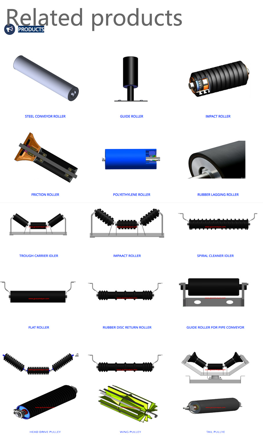
GCS Conveyor Supply offers a wide range of rollers to fit most conveyor applications - designed to the highest industry standards. Roller materials, lengths, diameters, and trough options can be customized to meet customer specifications. We are a manufacturer of slotted rollers, rollers, and frames. Our factory can do it all for bulk material companies, making it simple for everyone to design and order custom rollers and affordable matching roller frames online.
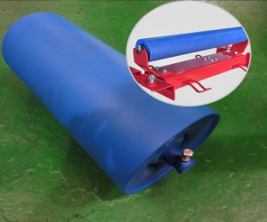
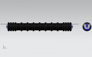
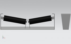
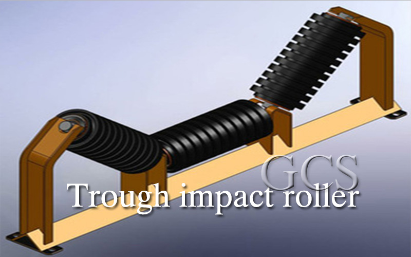
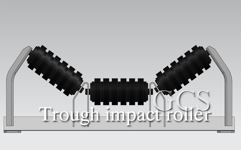
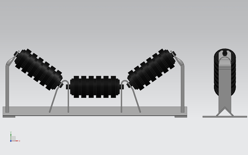
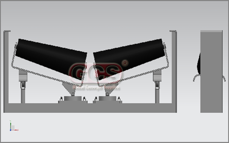
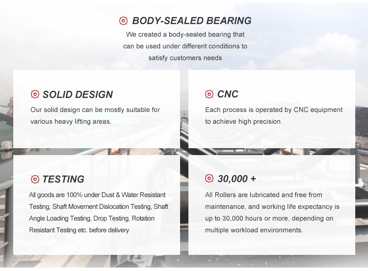
The Equal Trough impact idler, a conventional type carrier roller set, consists of three equal-length impact idlers supporting three rollers in one frame that is fixed to the conveyor structure. In quarry and mining applications, when large, heavy and sharp materials fall on the conveyor, they can impact and damage the belt, ultimately leading to downtime and higher replacement costs. Therefore, an impact idler is needed in the material impact area.
It is designed with a rubber ring to provide cushioning and absorb impact in the material impact area, minimizing damage to the belt.
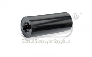
The common diameter of the roller tube is (mm)D89/102/108/133/152/159 or as per the order
Belt widths are available in (mm)500/650/800/1000/1200/1400/1600/1800 or customized
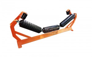
The impact idler sets are typically spaced 350 mm to 450 mm apart to provide overall support. It is installed in the first roller group at the conveyor's drop gate.
Applications
Conveyor impact rollers are used for belt conveyors to receive materials and reduce and slow down the impact of the conveyor belt, mainly designed for corrosive environments such as coal washing plants, coking plants, and chemical plants. The impact rollers have good corrosion resistance and if used in corrosive situations, their service life is five times that of ordinary rollers.
Get high-quality conveyor rollers, custom conveyor rollers, matching roller supports, and more you need.
Conveying Rollers Of Trough Idlers And bracket For Heavy Conveyor idler For Sale|GCS Brands
How Troughing Idlers Work
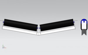
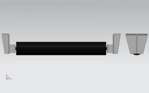
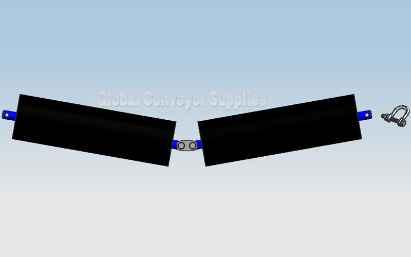
Troughing idlers consist of three or more idlers that guide the conveyor belt. They are found on the carrying side of the belt and are installed along the entire length of the conveyor. The troughing idlers work to keep the belt in the same configuration all along its length, which thus maintains the same cross-sectional area as the belt carries mined materials from their source to the drop off point. A troughing idler is comprised of a central idler roll, which has a fixed width, and two or more wing idlers located on each side of the central idler roll. The wing idlers can be adjusted up or down to change the toughing angle, which affects the depth of the trough created by the conveyor belt as it moves.
Benefits of Troughing Idlers
Troughing idlers offer two important benefits. First, the troughing idlers keep the belt’s shape consistent throughout its journey, which improves both stability and carrying capacity. Second, troughing idlers reduce the amount of material that may accidentally spill over the edge of the conveyor system, which improves productivity and also increases the safety of workers, who may be at risk from falling material while working near conveying equipment.
Trough Idler -SERIES RS/HRS
Bearing of Idlers
Numerical Tolerance
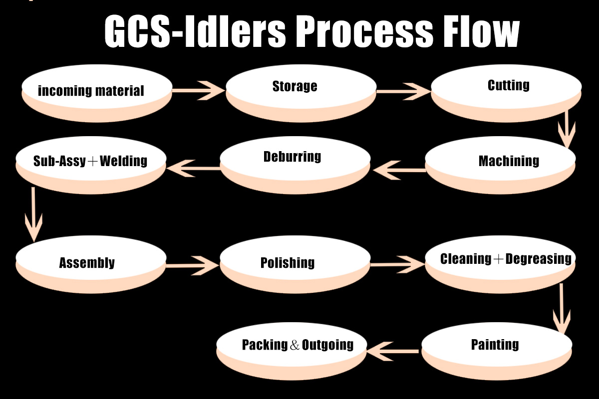
Process Flow
Bearing of Idlers
| Bearing size | Outside Diametermm |
O.D. Tolerance Class 0 (normal tolerance) |
| 6204 | 47.000 | 0/-11 |
| 6205 | 52.000 | 0/-13 |
| 6305 | 62.000 | |
| 6306 | 72.000 | |
| 6307 | 80.000 | |
| 6308 | 90.000 | 0/-15 |
| 6309 | 100.000 | |
| 6310 | 110.000 | |
| 6311 | 120.000 | 0/-18 |
Numerical Tolerance
|
Roll O.D. (mm) |
Diameter Tolerance (mm) | Wall Thickness (mm) | Wall Thickness Tolerance(mm) |
|
108 |
±0.60 |
2.75 | ±0.27 |
| 3.0 | ±0.30 | ||
| 3.25 | ±0.32 | ||
| 4.5 |
±0.35 |
||
| 5.0 | |||
|
114 |
±0.60 |
2.75 | ±0.27 |
| 3.0 | ±0.30 | ||
| 3.25 | ±0.32 | ||
| 5.0 |
±0.35 |
||
|
127 |
±0.80 | 3.5 | |
|
133 |
±0.80 |
3.5 | |
| 4.0 | |||
| 5.0 | |||
|
139 |
±0.80 |
3.75 | |
| 4.0 | |||
|
152 |
±0.90 | 4.0 | |
|
159 |
±0.90 | 4.5 | |
|
165 |
±0.90 | 5.0 | |
|
178 |
±1.0 | 5.0 |
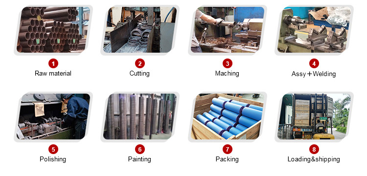
Process Flow
| Incoming Material | Cutting | Machining | Deburring | Sub-Assy+Welding | Assembly | Polishing | Cleaning+Degreasing | Packing&Outgoing |
| a) Material Type b) Thickness c) Appearance d) Roundness e) Straightness |
a) Appearance | a) Dimension b) Straightness c) Appearance |
a) Dimension (Customer Spec)b) Appearance c) Concentricity |
a) Deburring | a) Rotation Resistance b) Runout d) Dust Resistance |
a) Surface cleaning | a) Appearance | a) Quality As Per Packing Std |
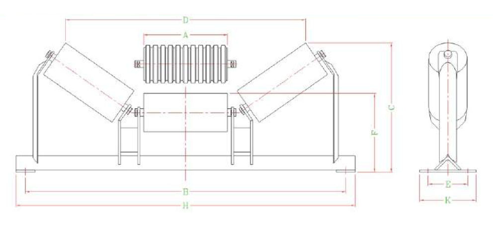
3 ROLL TROUGH IDLERS-178 DIAMETER
| Code No. | A | B | 20° | 30° | 35° | 45° | Base Angle Size | Shaft Dia. | Trough Mass R.P. | Total Mass | Shaft Dia. | Impact Mass R.P. | Total Mass | ||||
| C | D | C | D | C | D | C | D | ||||||||||
| XX-A1-3-D3A2-1200-YY | 442 | 1450 | 157 | 1326 | 229 | 1263 | 265 | 1200 | 315 | 1068 | 90 | 38 | 42.0 | 78.1 | 38 | 38.7 | 83.7 |
| XX-A1-3-E3A3-1350-YY | 494 | 1650 | 177 | 1472 | 259 | 1395 | 293 | 1336 | 350 | 1196 | 100 | 38 | 46.0 | 91.7 | 38 | 42.7 | 98.7 |
| XX-A1-3-E3A3-1400-YY | 500 | 1700 | 177 | 1492 | 259 | 1419 | 293 | 1358 | 350 | 1214 | 100 | 38 | 46.4 | 92.9 | 38 | 43.3 | 100.5 |
| XX-A1-3-E3A3-1500-YY | 547 | 1800 | 191 | 1628 | 289 | 1541 | 318 | 1486 | 383 | 1332 | 100 | 38 | 50.0 | 99.3 | 38 | 47.3 | 107.4 |
| XX-A1-3-F3A5-1600-YY | 567 | 2000 | 191 | 1688 | 289 | 1603 | 338 | 1526 | 405 | 1368 | 125 | 38 | 51.5 | 111.0 | 38 | 48.7 | 122.3 |
| XX-A1-3-F3A5-1800-YY | 631 | 2200 | 226 | 1888 | 328 | 1773 | 373 | 1700 | 439 | 1544 | 125 | 38 | 56.4 | 121.1 | 38 | 54.3 | 133.8 |
| XX-A1-3-G3A5-2000-YY | 706 | 2400 | 247 | 2082 | 364 | 1975 | 409 | 1904 | 488 | 1730 | 140 | 38 | 62.2 | 148.3 | 42 | 60.5 | 167.1 |
| XX-A1-3-G3A5-2200-YY | 785 | 2600 | 276 | 2310 | 405 | 2193 | 463 | 2098 | 552 | 1918 | 140 | 42 | 68.2 | 165.3 | 42 | 67.1 | 186.0 |
Note:XX-inputfor: RS or HRS.
YY-Inputforangle: 20° , 30° , 35° ,45°
Base angle size nominated is normal stock standard. Dimensions E and F vary with change in base angle size as tabulated below.
Code numbers shown are for plain trough idlers, for impact idlers change both" A'sH in code numbers to " B's
| Cade No | Nom A |
20° | 30° | 35° | 45° | Base Angle |
Shaft Dia. | Trough Mass R.P. |
Total Mass | Shaft Dia |
Impact Mass R.P. | Total Mass | |||||
| B | C | D | c | D | C | D | C | D | Size | ||||||||
| XX-A1-3-F3A5-1600-YY | 569 | 2000 | 191 | 1688 | 289 | 1603 | 338 | 1526 | 405 | 1368 | 125 | 48 | 57.8 |
127.9 |
48 | / | / |
| XX-A1-3-F3A5-1800-YY | 633 | 2200 | 226 | 1866 | 328 | 1773 | 373 | 1700 | 439 | 1544 | 125 | 48 | 62.7 | 139.0 | 48 | / | / |
| XX-A1-3-G3A5-2000-YY | 708 | 2400 | 247 | 2082 | 364 | 1975 | 409 | 1904 | 488 | 1730 | 140 | 48 | 68.4 |
167.4 |
48 | / | / |
| XX-A1-3-G3A5-2200-YY | 787 | 2600 | 276 | 2310 | 405 | 2193 | 463 | 2098 | 552 | 1918 | 140 | 48 | 74.4 |
181.9 |
48 | / | / |
| XX-A1-3-G3A5-2400-YY | 848 | 2800 | 293 | 2488 | 438 | 2351 | 492 | 2268 | 596 | 2060 | 140 | 48 | 79.1 |
193.9 |
48 | / | / |
| XX-A1-3-G3A5-2500-YY | 873 | 2900 | 303 | 2552 | 438 | 2437 | 513 | 2326 | 613 | 2122 | 140 | 50 | 81 |
201.8 |
50 | / | / |
| XX-A1-3-G3A5-2600-YY | 905 | 3000 | 321 | 2648 | 462 | 2523 | 526 | 2416 | 636 | 2198 | 140 | 50 | 83.4 |
208.1 |
50 | / | / |
| XX-A1-3-G3A5-2800-YY | 984 | 3200 | 347 | 2876 | 495 | 2731 | 569 | 2624 | 690 | 2392 | 140 | 50 | 89.5 |
222.7 |
50 | / | / |
| XX-A1-3-G3A5-3000-YY | 1050 | 3400 | 368 | 3064 | 527 | 2915 | 606 | 2802 | 740 | 2544 | 140 | 50 | 94.5 |
235.7 |
50 | / | / |
| co | |||||||||||||||||
| Note:XX-inputfor:RSorHRS | |||||||||||||||||
| YY-Inputforangle:20°,30°,35°,45° | |||||||||||||||||
| Base angle size nominated is normal stock standard.Dimensions E and F do not vary with change in base angle size as tabulated below. | |||||||||||||||||
| Code numbers shown are for plain trough idlers, for impact idlers change both"A's"in code numbers to"B's". | |||||||||||||||||
GCS conveyor roller chain manufacturers reserves the right to change dimensions and critical data at any time without any notice. Customers must ensure that they receive certified drawings from GCS prior to finalizing design details.
1.How do you make a conveyor roller?
Making rollers includes the following processes:
Pipe processing line, Welding-assembly-inspection line for rollers, Bearing seat, stamping assembly line, Bearing seat processing line, Spray paint-drying line. Please refer to the article How to make conveyor rollers? for details of the process.
2.How do I choose conveyor rollers?
When choosing rollers, we can choose rollers of different sizes and materials according to different scenarios and types of materials. More information please refer to How do I choose a roller conveyor?
3.What is conveyor belt rollers made of?
Conveyor belt rollers are made of steel, HDPE and many other materials.


Write your message here and send it to us